
LG DVD Player Service Manuals, Circuit Diagrams

On this page you can download the LG DVD Player repair manual, also you will find: GENERAL SERVICING PRECAUTIONS, ELECTROSTATICALLY SENSITIVE (ES) DEVICES, SPECIFICATIONS, REPAIR GUIDE, ELECTRICAL TROUBLESHOOTING GUIDE, SYSTEM TEST FLOW, POWER CHECK FLOW, WIRING DIAGRAM, CIRCUIT DIAGRAMS, CIRCUIT VOLTAGE CHART, MAIN P.C.BOARD.
| LG DP132 Service Manual | Download |
| LG LH-CX245(LH-CX245X)/LH-CX246(LH-CX246X) Service Manual | Download |
| LG DKE573XB (DE9353CEM) DKE574XB (DE9453CEM) DKE575XB(DE9553CEM) Service Manual | Download |
| LG DK676X/DK677X DVD VIDEO PLAYER Service Manual | Download |
| LG DVD5353 Service Manual Circuit diagrams | Download |
| LG BP340 Service Manual | Download |
| LG BPM55 Service Manual | Download |
| LG DF599 X DF9912EH Service Manual | Download |
| LG DK577XB/DK578XB/DK589XB (DK9753CEM/ DK9853CEM/ DK9966CEM) Service Manual | Download |
| LG DK673X (DV133KEM) Service Manual | Download |
| LG DK867/DK855/DK854/DV840 Service Manual | Download |
| LG DP122NU Service Manual | Download |
| LG DP170 Service Manual | Download |
| LG DP372B Service Manual | Download |
| LG DP372 / DP372B-N Service Manual | Download |
| LG DP381B, DP382B, DP383B Service Manual | Download |
| LG DP391B/DP392G Service Manual | Download |
| LG DS563X (DS9313CPM) Service Manual | Download |
| LG DVX286 / DV286 / DV286KService Manual | Download |
| LG DVD 5185 (DV6812E4) Service Manual | Download |
| LG DVD6054/DVD6184 (DV7511E6S/DV7811E6S) Service Manual | Download |
| LG GoldStar DVD5185(DV7311E4L) Service Manual | Download |
| LG HB954TB (HB954TB-AD / SB94TB-C/F/S/W) Service Manual | Download |
| LG HB954WA (HB954WA / SB94WA-C/F/L/R/ W) Service Manual | Download |
| LG HT904TA (HT904TA, SH94TA-F/S/C/W) Service Manual | Download |
| LG LGDVT418 Service Manual | Download |
| LG LPA-735/DP171/172G/BP/173G Service Manual | Download |
| LG RCT689H VCR+DVD RECORDER Service Manual | Download |
| LG RHT497H RHT499H Service Manual | Download |
Basic parameters, design and repair of DKS-6000/6001/6100/6101 players
- playable discs: CD, DVD, DVD±R, DVD±RW, CD-R, CD-RW, MP3, WMA, JPEG, DivX;
- connectors: RCA outputs of 5 channels, video and component video outputs, S-Video, digital coaxial/optical outputs; microphone input on the front panel;
- modes: Dolby Digital, MPEG 2, DTS, Dolby Pro Logic, Dolby Pro Logic II; video 4:3, 16:9, progressive scan, PAL/NTSC/auto;
- signal/noise ratio: no more than 0.008%;
- dynamic range: 100/95 dB (DVD/CD);
- power supply: 110...240 V/.50/60 Hz, 14 W.
The appearance of the DKS-6100B model with the casing removed is shown in Fig. 1, the assembly drawing of the DPE7 mechanism is shown in Fig. 2, and the numbers of parts and components of the mechanism, the need for replacement of which may arise during repairs, are given in Table 1

The DPE7 mechanism uses a PVRE502W optical unit from MITSUMI with a tracking actuator sensitivity of 0.82 mm/V and a focusing actuator of 1.2 mm/V. Output signal parameters: HF - I V, tracking errors - 2.4 V/0.14 V (DVD/CD), focusing errors - 0.7/0.59 V (peak values). The appearance of the block is shown in Fig. 3.
There are other modifications of the disk drives used in the DP-7 mechanism: SLED DP-7 (Part No. 3041R-M002U), SLED DP-7A (Part No. 3041R-M016D), SLED DP-7-HZ (Part No. 3041R-M016E ), SLED DP-7C DI (Part No. 3041R-M016I), SLED DP-C (SAMSUNG) (Part No. 3041R-M016R).
To replace the loading motor BXZ3B01 from SANKYO, the following engines are suitable: RF-300-CA-11440 from MABUCHI, MDN3BL3CSA from MATSUSHITA, PC200DG-21667 (JOHNSON), M25E-4 (MITSUMI). Motor parameters: Uwork = 1...6 V (Unom = 3 V), Iхх/Irab=0.018/0.065 A, rotation speed - 3000/2400 rpm, Pout=0.11 W.
Parameters of the positioning engine of the optical unit RF-300EA-1D390 from MABUCHI:
Urab=1.6...6.5 V (Unom = 2 V), Ixx/Irab=0.015/0.052 A, rotation speed - 2200/1710 rpm, Pout=0.02...0.6 W .
The block diagram of the DKS-5500/5600/6000/6001/6100/6101 players is shown in Fig. 4. The basis of the circuit is the LSI IC501 ES6698F of the Vibrato-II family from ESS Technology, Inc. The family chips (ES6230SF, ES6629F/FD, ES6688FA/FAD, ES6698F/FD, etc.) are made in PQFP-208 packages and differ in functionality (MPEG-4 or DivX decoding, DVD-Audio/TV encoders/DTS). LSI is a single-chip solution for DVD applications and includes the following components: data reading channel, error corrector (ECC - error checking and correction), servo processor (Servo DSP), control system microprocessor (MCU), MPEG-2 decoder, interlaced scan converter progressive 480r/576r. The LSI is built on a dual programmable multimedia processor (PMP) with a 32-bit RISC core and a 64-bit signal processor (DSP). Main features of LSI ES6698F:
- provides focusing, tracking and positioning of the optical unit, rotation of disks in CLV/CAV modes;
- error correction, demodulation of EFM/EFM+ signals;
- built-in ADCs and DACs in autoregulation systems;
- 10-bit video DAC (54 MHz, NTSC/PAL);
- decoding signals from DVD, DVD-VR, VCD1.1/2.0, SVCD, CD-ROM, CD-R/RW, DVD±R/RW. DivX, DVD-Audio;
- up to 7+1 audio channels;
- graphics controller with support for 256 colors;
- support for sound standards Dolby Digital (AC-3), Dolby Pro Logic, Dolby Pro Logic II, DTS, MPEG-AAC, DVD-Audio.
The circuit diagram of the control system and DSP of the DKS-6000/6001/6100/6101 models is given in the archive (see at the end of the article) (in the DKS-5500/5600 models there is practically the same circuit), in addition to the IC501 LSI, the circuit includes:
- IC500 MBM29LV160TZ-90/320TZ-90: 16 M CMOS Flash memory (2 M x 8/1 M x 16 bits) from FUJITSU;
- IC502 NJM2279: video switcher 3 inputs to 2 outputs with built-in amplifiers (Ku=6 dB) from JRC. The bandwidth of both channels at the -1 dB level is 0.1.5 MHz, the structure of the microcircuit is shown in Fig. 5.

In the circuit under consideration, the microcircuit is used as a splitter/video amplifier for Y and G/Y signals;
- IC503 HY57V651620B: SDRAM type RAM with a capacity of 4 x 1 M x 16 bits from HYNIX;
- IC509 KS24C021CS: EEPROM 256 x 8 bits from SAMSUNG;
- IC511 74HCT244: two 4-channel logic buffers with three states (logic "0", logic "1", high impedance), in the circuit in Fig. 5 uses three channels of the microcircuit in the input signal broadcast mode;
- IC512 KA741: operational amplifier from FAIRCHILD;
- IC516 CS5331: stereo ADC from Cirrus Logic (18 bits, dynamic range 94 dB, sampling rates 32 kHz, 44.1 kHz, 48 kHz, THD - 0.003%).
The structure of the CS5331 chip is shown in Fig. 6. It includes: a sample-and-hold device (S/H), a low-pass filter (LP Filter), a DAC (DAC), comparators (Comparator), a decimation digital filter (Digital Decimation Filter), a high-pass filter (High Pass Filter), output serial interface (Serial Output Interface). In the circuit, this ADC is used to convert the signal from an external microphone in monophonic mode (karaoke mode).

It is convenient to check the supply voltages supplied to the control system and DSP at the contacts of connector CN503.
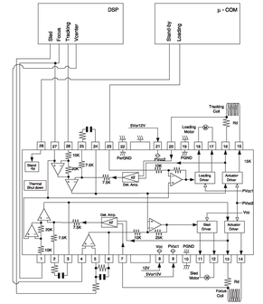
The schematic electrical diagram of the HF unit and part of the auto-regulation system for models DKS-6000/6001/6100/6101 is shown in the archive (the diagram of this unit for models DKS-5500/5600 is almost the same). The RF unit and the control system for the motors and actuators of the optical unit are implemented on the IC401 ES6603 microcircuit of the Vibrato II family from ESS. Control of the disk (spindle) motors, positioning, tracking and focusing coils of the optical unit is provided by the IC404 BA5954 microcircuit from ROHM, the structure and circuit diagram of the microcircuit is shown in Fig. 7.
The circuit diagram of a switching power supply (SMPS) of the DKS-6000/6001/6100/6101 models is shown in the archive; the DKS-5500/5600 models use almost the same power supply. The SMPS is made according to the flyback voltage converter circuit on the IC101 ICE2B0565 chip in the PG-DIP8-6 package from INFINEON, Part No 0IPMGIH004A. Since there is no list of elements in the service manual of the players (as in most other manuals for LG DVD players), Part No. of the microcircuit and its type are taken from the list of elements of TOSHIBA DVD players (models SD-530ESE/ESB/ESY), in which the chip is used "filling" of one of the models of LG players (Part No. 79096694 according to TOSHIBA classification).

The structure and circuit diagram of the ICE2B0565 microcircuit is shown in Fig. 8. It includes a standby power unit (Low Power Standby), a power control unit (Power Management), a soft start circuit (Soft-Start Control), a PWM controller with current control mode (PWM output current body with low impedance (Precise Low Tolerance Peak Current Limitation), protection circuits (Protection Unit), power field-effect transistor of the CoolMOS type. Here are some features and parameters of the microcircuit:
- switching frequency 67...100 kHz with duty cycle up to 72%;
- protection circuits for current in the load, against overvoltage and overheating;
- “soft” control to reduce interference;
- CoolMOS transistor parameters: Uсi=650 V, Rds on=4.7 Ohm, Рout=23 V.
NONOY BAGUISI (Wednesday, 15 April 2026 05:15)
SCHEMATIC DIAGRAM FOR LG DVD 3D HOME THEATER MODEL BH6530T
r.krishnaraj (Tuesday, 03 June 2025 04:21)
how to get digram